Cult of Sea

Maritime Knowledge base

  • Home
  • Knowledge base
    • Bridge Equipment
    • Cargo Work
    • Deck
    • General
    • Gmdss
    • Maritime Law
    • Marpol
    • MLC 2006
    • Meteorology
    • Navigation
    • Safety
    • Security
    • Ship Construction
    • Ship Handling
    • Ship Stability
    • Shippie’s Escape
    • Surveys
    • Tankers
  • Colreg’s (ROR)
    • Index (Colreg’s)
    • Part A- General
      • Rule 1 – Application
      • Rule 2 – Responsibility
      • Rule 3 – General Definitions
    • Part B- Steering and Sailing
      • Section 1 (Rule 4 -10)
        • Rule 4 – Application
        • Rule 5 – Lookout
        • Rule 6 – Safe Speed
        • Rule 7 – Risk of collision
        • Rule 8 – Action to avoid collision
        • Rule 9 – Narrow Channels
        • Rule 10 – Traffic separation schemes
      • Section 2 (Rule 11 – 18)
        • Rule 11 – Application
        • Rule 12 – Sailing vessels
        • Rule13 – Overtaking
        • Rule 14 – Head on situation
        • Rule 15 – Crossing situation
        • Rule 16 – Action by give-way vessel
        • Rule 17 – Action by stand-on vessel
        • Rule 18 – Responsibilities between vessels
      • Section 3 (Rule 19)
        • Rule 19 – Conduct of vessels in restricted visibility
    • Part C- Lights and Shapes
      • Rule 20 – Application
      • Rule 21- Definitions
      • Rule 22 – Visibility of lights
      • Rule 23 – Power-driven vessels underway
      • Rule 24 – Towing and pushing
      • Rule 25 – Sailing vessels underway and vessels under oars
      • Rule 26 – Fishing vessels
      • Rule 27 – Vessels N.U.C or R.A.M
      • Rule 28 – Vessels constrained by their draught
      • Rule 29 – Pilot vessels
      • Rule 30 – Anchored vessels and vessels aground
      • Rule 31 – Seaplanes
    • Part D- Sound and Light Signals
      • Rule 32 – Definitions
      • Rule 33 – Equipment for sound signals
      • Rule 34 – Manoeuvring and warning signals
      • Rule 35 – Sound signals in restricted visibility
      • Rule 36 : Signals to attract attention
      • Rule 37 – Distress signals
    • Part E- Exemptions (Rule 38)
      • Rule 38 – Exemptions
    • Part F – Verification of compliance with the provisions of the Convention
      • Rule 39 – Definitions
      • Rule 40 – Application
      • Rule 41 – Verification of compliance
    • Annexes
      • Annex 1 – Positioning and technical details of lights and shapes
      • ANNEX II – Additional Signals for Fishing Vessels Fishing in Close Proximity
      • ANNEX III – Technical Details of Sound Signal Appliances
      • ANNEX IV – Distress Signals
  • Glossary
  • Contact
You are here: Home / Tankers / Tankscopes – Tanker Instruments
Tankscope

Tankscopes – Tanker Instruments

Non-Catalytic Heated Filament Gas Indicators (Tankscopes)

Operating Principle

The sensing element of this instrument is usually a non-catalytic hot filament. The composition of the surrounding gas determines the rate of loss of heat from the filament, and hence its temperature and resistance.
The sensor filament forms one arm of a Wheatstone Bridge The Initial zeroing operation balances the bridge and establishes the correct voltage across the filament, thus ensuring the correct operating temperature During zeroing, the sensor filament is purged with air or inert gas that is free from hydrocarbons. As in the Explosimeter, there is a second identical filament in another arm of the bridge which is kept permanently in contact with air and which acts as a compensator filament.Tankscope

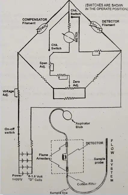
The presence of hydrocarbon changes the resistance of the sensor filament and this is shown by a deflection on the bridge meter. The rate of heat loss from the filament is a non-linear function of the hydrocarbon concentration and the meter scale reflects this non-linearity. The meter gives a direct reading of % volume hydrocarbons. When using the instrument, the manufacturer’s detailed instructions should always be followed. After the instrument has been initially set at zero with fresh air in contact with the sensor filament, a sample is drawn into the meter by means of a rubber aspirator bulb. The bulb should be operated until the meter pointer comes to rest on the scale (usually within 15-20 squeezes) then aspirating should be slopped and the final reading was taken. It is Important that the reading should be taken with no flow through the instrument and with the gas at a normal atmospheric pressure.
The non-calatytlc filament is not affected by gas concentrations In excess of its working scale. The instrument reading goes off the scale and remains in this position as long as the filament is exposed to the rich gas mixture.

Related Article:   OIL TANKER OPERATIONS (Discharging) - Conventional Tanker Basics

Instrument Check Procedures

The chocking of a non-catalylic heated filament instrument requires the provision of gas mixtures of a known total hydrocarbon concentration.
The carrier gas may be air, nitrogen or carbon dioxide or a mixture of these Since this type of instrument may be required to measure accurately either low concentrations (1%-3% by volume) or high concentrations (greater than 10% by volume) It is desirable to have either two test mixtures, say 2% and 15% by volume, or one mixture between these two numbers, say 8% by volume. Test gas mixtures may be obtained in small aerosol type dispensers or small pressurised gas cylinders, or may be prepared in a special test kit.

The measuring circuit is a balanced Wheatstone’s bridge.

Three major steps must be taken before the samples are drawn into the instrument for analysis:-

  1. The detector chamber must be swept free of C/H gases and filled with inert gas or air.
  2. Batteries must be turned “on”, and the proper voltage applied to the bridge.
  3. The bridge must be. balanced to zero deflection on the meter with IG or fresh air in the filament chamber.

The MSA tank scope is sensitive to tilt, so it is important to keep the instrument in a normal, upright position during operations or there may be a significant error in instrument readings.

Related:

  • Inert Gas on board Tankers - All you need to know!
  • Tanker Terminology used in Shipping
  • International Institutions and their Association…
  • Gas Tanker - Types, Tanks, Reliquefaction &…
  • Frontal Depressions - Types of Fronts, Weather…
  • Recommended Practices for Storage and Transport of…

By Cult of Sea Filed Under: Tankers Tagged With: compensator, current, filament, gas, pellistor, sensor, tankers, tankscopes, wheatstone

Comments

  1. shashi says

    November 22, 2022 at 1:23 pm

    can you tell me more in detail about compensator filament

    Reply

Leave a Reply Cancel reply

Your email address will not be published. Required fields are marked *

Simple Colregs COS Ad

Join Our List

Subscribe to our mailing list and get interesting stuff and updates to your email inbox.

Powered with ♥ by Cult of Sea

instagram-button

What others are reading

Ship's magnetic compass

Ship’s Magnetic Compass – Dry and Wet Compass with their care, maintenance and bubble removal

Ship's Waterplane, Block, Midship and Prismatic Coefficient

Coefficients of Form – Ship’s Waterplane, Block, Midship and Prismatic Coefficient

I haven’t been everywhere, but it’s on my list

Hot work on ships

Hot Work – Definition, Responsibility, Process and Risks On-board Ships

Anti Exposure Suit

ISM Code

ISM Code – All you should know about International Safety Management Code

EPIRB

EPIRB – Emergency Position indicating Radio Beacon

GMDSS Radio Equipment Requirements on Ship as per SOLAS

Cold Work

Part F - Verification of Compliance

Rule 39 – Definitions

Part C Lights and Shapes

Rule 29 – Pilot vessels

Part D - Sound and Light Signals

Rule 33 – Equipment for sound signals

Powers of Inspectors – Dock Worker Rules 1990

Leave

Entitlement to leave – MLC 2006

Part D - Sound and Light Signals

Rule 36 : Signals to attract attention


About Us | Terms | Contact Us | Sitemap | Marine Glossary (BETA)

Cult of Sea®™ · Made with ❤ by a small band of sailors