Double hull tankers
The double hull design has many advantages over the more traditional single-hull designs, performing better in the low-speed collision or grounding situations. Looking at 30 tanker groundings between 1969 and 1973, a study by the U.S. Coast Guard concluded that 96 percent of the spills could have been prevented with double hulls. How these monstrous tankers can so successfully avoid oil spillage is a direct outcome of their engineering and design.
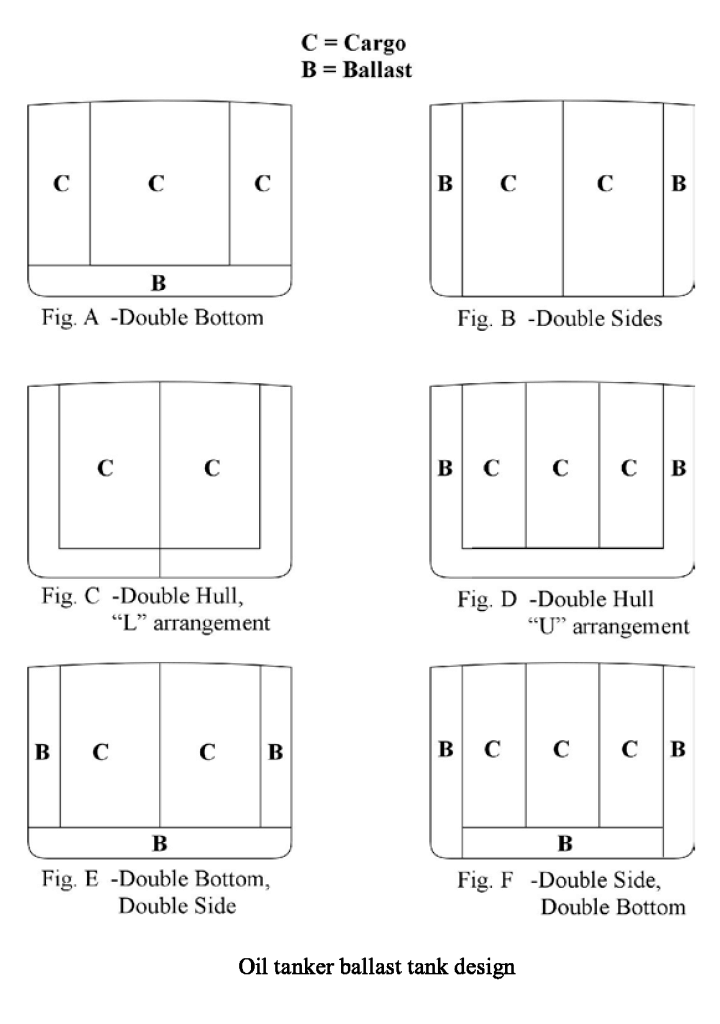
There are two types of double-hull ballast arrangements:
- The first is the “L” type arrangement, where the ballast is the space between the outer and inner hulls. This design has the potential for large off-centre weights if any portion of the cargo in either the port or starboard tanks is lost. This can lead to instability and in rough seas potentially to capsize.
- The second type of double-hull tanker is the “U” type, in which the ballast is one continuous divider between the outer and inner hulls. This design is much more stable under spill conditions, and because it separates the cargo into smaller containers (assuming standard tanker size), less oil will spill if one tank is ruptured.
Both configurations of double-hulled tankers achieve the same, major objective. During a low-speed collision, because the outer and inner hulls are separated by at least 6 feet, typically only the outer hull will rupture. This leaves the inner hull intact and consequently, the oil that it contains. So theoretically, it is possible for a double-hull tanker to run aground, and not spill any oil. However, a severe accident such as the grounding of the VALDEZ would probably puncture both hulls and spill oil. But as far as protecting more efficiently against oil spills in all accident scenarios, double hulls are far superior to their predecessors.
In a study recently performed by scientists, the strength of double-hull tankers under grounding conditions was examined. The researchers chose four double-hull and two single-hull tankers of conventional type and modelled their design characteristics using various calculation models.
Then, varying the parameters of stresses and other factors involved in tanker groundings they determined which design was more effective in preventing spills. They found that all four double-hull designs were safe, and would not leak oil upon grounding. When compared to the results with single-hull designs, they also found that the older design was far more likely to spill oil when grounded.
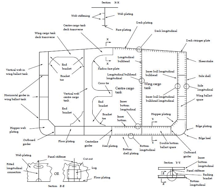
Not only are single-hulled tankers weaker when subjected to grounding conditions, but also they are harder to clean. The internal sides of single-hull tankers are a matrix of support beams and girders.
These help support the ship but make it difficult to clean out the tanks. In a double-hull tanker, the insides of the tanks are smooth (supports are between outer and inner hulls) and subsequently side clingage is minimised, making tank cleaning much easier. Periodic cleaning prevents excess corrosion and makes the tanks more accessible to mandatory and company-sponsored inspections. Together, this reduces the risk of an oil spill.
In addition, the void between the two hulls is subject to minimal corrosion. This is accomplished by the continuous evacuation of water from this space using a bilge pump or a similar device. Making the newer design more corrosion resistant accomplished a number of things. First, it preserves the integrity of the design for a greater amount of time increasing the longevity of the ship. Second, it reduces the need for maintenance and inspection of the hulls.
 @Figure Credit DanTN, Nav Arc
In addition, the void between the two hulls is subject to minimal corrosion. This is accomplished by the continuous evacuation of water from this space using a bilge pump or a similar device. Making the newer design more corrosion resistant accomplished a number of things. First, it preserves the integrity of the design for a greater amount of time increasing the longevity of the ship. Second, it reduces the need for maintenance and inspection of the hulls.
Paired with the overwhelming spill prevention aspects of double-hulls are also some drawbacks. The void between the two hulls discussed above produces some immediately obvious problems. Since it is a large vacant space adjacent to a large concentration of hydrocarbons (in the cargo tanks) it is possible that combustible vapours accumulate in this void. The outcome of a collision or grounding would then be disastrous, a spark producing not only an explosion of the vapours in the void but also a breach of the inner and outer hulls. This could further lead to the ignition of the cargo. Pollution from the burning oil slick would be disastrous, not to mention the sheer amount of oil spilled by such an explosion. Regulatory controls such as the Oil Protection Act of 1990 have accommodated for such a possibility, prohibiting any sort of cargo transport piping in the area between the two hulls. Regardless, a small risk remains.
1 self-propelled double hull shuttle tanker (capacity 25,000 – 30,000bbls) Draft Max of 5.2m.